12 October, 2016

Gennaker

I've always wanted a "light wind" device like Gennaker, Spinnaker or Code-0. However the more you will think about these sails, the more you will be confused what is the best option for you. I'm not any kind of a racer so I wanted just one and the most usable sail for a light wind conditions.
After a few months of discussion with different sail makers I had decided for the most general purpose sail Gennaker G1 on the roller furler from the polish sail maker SailService.

The rig dimension of the Phobos 21 with a standard bowsprit is:

I = 7800mm
J = 2720mm
LP = 8200mm (If I will subtract the height of the roller furler Ronstan 60 series, the sail luff can be 7900mm maximum)
B = 6000mm (Horizontal dimension between the bowsprit and sheet's block)
Sail foot ~5100mm

rig dimensions

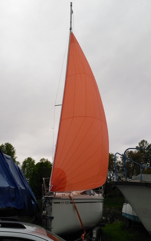
Gennaker G1 with straight luff from SailService

As you can see, the shape of this sail is slightly different than regular Gennaker. That's because with the regular shape, you need a "top-down" roller furler which is a bit expensive. For our size of the boat, the Ronstan 60 series with 8mm anti-torsion rope is just enough, but the sail needs to have a straight luff! This sail shape is also called as Code-D. See the theoretical wind angles bellow.


Code-D wind angles (trade mark of  Delta Voiles)


Ronstan 60 series and 8mm anti-twist/anti-torsion rope.

The sail cloth for the winds up to ~15 knots has been chosen the Contender nylon Superkote 75 - orange color.

Finally arrived at the beginning of the year

Pretty long luff in comparison with 4 year daughter :-) 

SailService sail bag

The hard work had to wait till the warmer months so I could prepare the mast and boat with the necessary hardware.

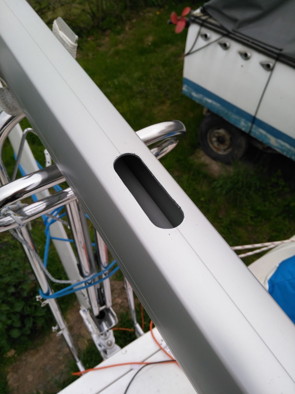
At first I had to drill a hole for the halyard - Holt-Allen HA28 40mm sheave box.

mask the mast with the tape to prevent scratches
Cutting the hole for the sheave box was pretty easy. Drill the holes at the ends of the groove and then use the jigsaw to cut through the remaining material. Then finish the groove with the file.

finished groove
Then insert the sheave box and drill the holes for the stainless rivets.

finished halyard block
Fortunately, the mast is already equipped with the line exit at the mast step, so I just had to use the mainsail halyard to pull the new line through the mast.

Harken furler with the snap-shackle attached to the bowsprit eye

The continuous furler line is led aft on the port side and ended with a small block that is attached to the pushpit with a bungee cord. This bungee cord will hold the line in the jaws of the furler and helps a little from free wheeling. When you need to unfurl the Gennaker, just push the bungee cord a bit forward and pull the sheet.

continous furler line and Gennaker sheets with cam cleats

The sheets from Gennaker lead to the 40mm blocks attached to the pushpit and then to the Ronstan RF5010 cam cleats. The cleats are fastened through the deck inside the cockpit lockers.
I can use the main winches instead of the cam cleats, but this is more convenient to keep all the sheets from the Genoa and Gennaker cleated and in the stronger winds, I can still handle the sheets by hands without any trouble.

first test

first test

During the summer season we have used it plenty of times, even single handed, and I must say, it's worth the money. It's a great upgrade to every boat!

running with mainsail - Orlik dam

close reach on Adriatic sea

Adriatic sea
As you may notice, there are white velcro tapes near the clew. This is a clever idea of the sail maker that keeps the Gennaker from unfurling.

One hint on the Gennaker sheets - the rope should be as light as possible so they will not pull the clew down in light wind. I was lucky enough that I was able to get 8mm dyneema core sheets from Lanex during a boat show for a very low price.

great time sailing

07 September, 2016

Building custom instruments pod

A friend of mine Jirka, with his own Phobos 21 called "Lente" build this custom instrument pod on the top of the companionway hatch.


So with his kind permission I'm sharing his building process.

He used the 3mm ABS board laminated with an acrylic film. These boards are often used as an advertising sign.
Then he formed the curves using the hot air gun (around 200°C). Side walls are glued and then polished. Finally, it has been straightened inside the pod using the fiberglass and epoxy.


paper template

gluing the side walls

template for the instruments holes

finished pod with fiberglass reinforcement

installed instruments

finished pod (depth, compass, wind)

If you have any enhancements, please don't hesitate and send it to me. I would be more than happy to share it. Phobos 21 is a wonderful class.

23 May, 2016

Centerboard noise reduction

I call this post a noise reduction, but it's more like a hummer banging reduction that centerboard produce when you are cutting through the waves.
That's because the centerboard iron plate has too much play in the trunk, almost 10 mm on each side and when the boat heels to the opposite side, that small gap can make noticeable banging sound.

Searching through the internet, I've found several solutions like a piece of rubber or stainless steel spacers with HDPE sliding pads as on Avar Yacht A25 of a friend of mine:

Avar Yacht A25 centerboard spacers -
two pairs in front and back of the steel plate

This is the stainless steel centerboard used on TES 678, but same design is used on Phobos yachts:

TES 678 staineless steel centerboard

However, last year we met a sailor with his older Phobos 24 and he fixed it with just an ordinary carpet. It did not sound very marine solution, but he told me he has it for more than 6 years without any problems.

Luckily we have a trailer with two support bunks so I can reach the centerboard trunk easily.
Using the hot-knife a.k.a. modified soldering iron, I cut two 2cm wide and 1m long stripes of the ordinary fully synthetic carpet and glued it with Sikaflex 291i covering the area starting just behind the centerboard pin to the end of the centerboard.

centerboard with carpet on the walls

detail of the carpet
The banging sound disappeared completely so we can now enjoy the silent nights with a dropped centerboard.

20 May, 2016

Solar power extention

During our trip in the hot Adriatic seas, we have found out, that our actual 50W solar panel is not sufficient to be ultimately shore power independent. During that hot summer days we were able to keep the fridge running only for like 12 days before I had to recharge the battery from the shore.

One of the issue that was that our boom tent partially covered the panel during the day, so it has prevented the proper function.

So I've decided we need more solar panels. The question is the where to place it?
At first I was thinking putting them to the mast support or on the backstay.

solar panel on the aft mast support

solar panel on the backstay

However all these positions needs some maintenance and I think it's not really handy for a trailer-sailor when you need to simplify all the mast raising/lowering tasks.

A final decision was to get the semi-flexible panels and put them on the top of the cabin. The only possible free area for them is besides the mast base. Due to area limitation I was able to find these two suitable 20W ETFE semi-flexible panels from China with dimmensions of 600x300x2.5mm. You can also walk on these!

20W EFTE semi-flexible panel - model LS-20FX1

The installation is again drill-less using the 19mm 3M VHB acrylic double sided tape 49xx series, which has already proved to be working very well even on our hollow non-skid surface. It's just needed to degrease the surface with the isopropyl alcohol.

3M VHB double sided tape on the back of the panels

final placement

final placement
The next task was to create a junction box. I've created a simple circuit board inside a plastic junction box and glued it carefully under the existing 50W solar panel using Sikaflex 291i. It's important that this junction box is completely watertight to prevent any corrosion.

With parallel connected panels, each string to be connected in parallel should have its own blocking diode. This prevents current flowing from one parallel panel into a lower-current panel (shaded) and therefore helps to minimize mismatch losses arising in parallel connected arrays.

The best blocking diodes are Schottky's rectifying diodes like SB540 or similar. They have lower forward voltage drop around 0.3V instead of regular rectifying diodes which has around 0.7V.


junction box scheme with blocking diodes 

The new 20W panels are equipped with cables including the MC4 connectors already, so I've just bought two 1m long extension cables with MC4 connectors, cut them in half and used them as an input connectors.

inside the junction box

One hint here: to protect the circuit board from corrosion, it's necessary to coat the copper and the components with soldering rosin (flux) soluted in alcohol.

junction box glued with Sikaflex

The last step was to replace the old deck socket I've installed before. I bought some cheap China copy and the contacts corroded very badly just after a first season.

So I've decided to use some better connector with gold plated contacts and decided to use these type from Philippi Marine. You can also buy just the angular housing from Philippi and cheaper Weipu WA22 type connectors, which are not labeled "marine" as a primary use, but I believe it's the same quality - gold plated 16 Amps! That's what I did.

Weipu WA22 IP67 16Amp connector

The first test looks very promising and I hope that with a total of 90W, we will be shore power independent, at last.

28 April, 2016

3D model and panoramic view

The Dalpol boatyard has just released a 3D model of their sailboats. It's not very accurate compared to the real boat, but still cool. Check this Link to page if the preview bellow does not work.


This is the 360° panoramic view of the charter version:


and the deluxe version:


More information on the official website.

25 April, 2016

Water tank modifications

The factory water tank installation, we have in the bow, had a few issues I wanted to address.
At first, the water tank is not horizontal and the front of the tank is slightly raised due to the shape of the V-berth storage, but tank vent is on the lower side of the tank. That leads to an air pocket and we could not fill the whole tank (54 liters).

The second problem is that water pump. Under certain amount of water, it's unable to pump out the every lasts of the water, leaving around ~5 liters in the tank.

Original tank vent and pump

The third problem is the supply hose. It's going from port side and because it's just laying without proper installation, this "arrangement" creates puddles of the stinky water. Not even helping the winterizing process.

Original vent & fill hose "alignment" problems
So the first step is to relocate the tank vent to the most top it could go. I simply used slightly modified plastic thru-hull near the edge of the tank.

New ventilation hole - modified plastic thru-hull 

Then routed a new vent hose on the top of V-berth storage and installed the new water pump Vetus WP1208.

New vent hose
During the electrical installation, I've found out another "bug". I know that the boat does not fully meets the marine standards for wiring, but this .... ??

Shame on you Dalpol electrician!

The water pump has a pressure switch which can be used later, when we would like to have a stern shower or something similar, however we have the faucets with the electrical switch already, so there is no need for it now.

And this is the final installation with the proper hose alignment allowing us to have more water on board :-)

From the top: vent, output & intake

Fill hose and vent hose (behind) properly secured
The last benefit of this modification is that the output hose is now going to the top of the storage locker and not from the bellow as was originally installed, so when there will be some water ingress from the depth sounder, it will not flow around the whole hull and stays in the locker.

Updated 24.10.2016 - To prevent the frequent starts of the pump and to increase its service life, I've installed the small accumulator tank under the sink in the galley. It's connected directly to the hose which leads to the galley faucet.

expansion tank

07 April, 2016

Sliding hatch fix

Since the beginning, we have observed that under heavy rain, the water gets its way into the cabin though the sliding hatch. The problem was later identified as a manufacturing flaw, because the beneath of the hatch is not flat and drops coming from the edges of the hatch flows back to the cabin.
The other issue is the weak corners and after a few months of light use, the front corners cracked against the ends of the sliding track.

The problem is the small thick of the laminate on the lips with the soft Airex coring behind. So I've decided to remove small piece of the coring and fill it with thickened resin.


Here you can see the cracks on the corners (gelcoat already sanded)

Weak hatch corner without core.

With masked underneath I've filled the gap with thickened resin.

Final stage painted with gelcoat and buffed.

To fix the water intrusion, I've installed 4mm height self-adhesive brush pile seal on the track of the sliding hatch. The other benefit is that I can now slide the hatch very easily.
The second brush seal track was also added at the edges of the sliding hatch, which helps the water to drop off the on the edge of the hatch.

Brush track.

Seal is working just fine.

This is the view under the sliding hatch cover.

15 January, 2016

Hull vinyl wrapping

This is a nice example, how to change the color of the hull pretty fast and easy.


I'm not sure about the price, but it will protect the hull from UV rays and I can imagine changing the hull color every two or three years :-)