21 June, 2017

Autopilot and tiller lock

You maybe wonder why do I have to install both the tiller lock and the autopilot at the same time. The simple answer is that the tiller lock was installed last year and I forgot to put it here, sorry :-)

The tiller lock is a wonderful thing when you need single hand the boat and let the tiller go for some simple tasks. There are numerous locker designs, but there is one with a very neat solution called the TillerClutch by WaveFront Marine. It's very easy to operate and is specially shaped to fit tiller shafts that are rounded, like the 1" tubing I have on the boat.
I've drilled and tapped the holes bellow the shaft and simply screwed the clutch onto it.

TillerClutch mounted bellow the tiller shaft

The control lines are attached to the stern rails with carabiner on one end and the v-cleat on the other to adjust the tension of the line. The installation manual suggests both ends with the v-cleat for easier handling, but this is working fine for me so far.

Control lines

Detailed view

This winter, however, my wife bought me a proper autopilot from Raymarine, model ST1000+. That's definitely a different level of single handing and it provides more time for other tasks instead of holding the course by hand. The big advantage over the TillerClutch is that it keeps your boat on the specific course, no matter how the wind or current changes.

Mounting it is the other story and after a lot of "head scratching" sessions in the cockpit, I've installed it without any additional Raymarine removable pedestals or extension rods, however, I had to fabricate a custom tiller bracket from the 3mm thick and 20mm wide stainless steel plate to cope the specific shape of my tiller shaft. Then drilled a hole for the shortened tiller pin and welded it in place.

Then I had to drill the 13mm hole into the cockpit locker lid, prepare the thickened epoxy and glue the brass mounting socket.

Mounting socket position

Epoxy around the socket

The next step was to mount my custom tiller bracket using the existing screws for v-cleat for the rudder lifting line. It's two small M4 screws, but seems it's holding fine.
At first I've mounted the bracket directly under the tubing, but there was a huge flexing to the sides so I had to add a small piece of the U profile to follow the shape of the tubing and reinforce the bracket to prevent the wobble.

U profile reinforcement between tiller shaft and tiller bracket

Tiller bracket

Autopilot in place


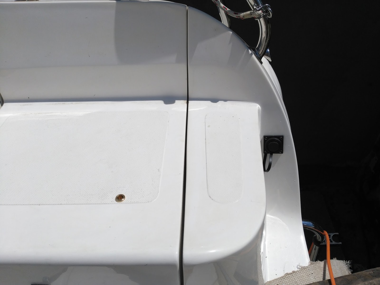
And finally install the electrical socket on the stern where it shouldn't interfere with anything. The cable is routed together with other cables to the main distribution panel and is now using the same switch as for the depth sounder. I've just replaced the 5A fuse with 10A.

Socket cable
The Raymarine ST1000+ is capable of receiving the speed through the water over the SeaTalk protocol, but it's not connected yet. I suppose it will not make much difference in the tiller adjustment speed. Keeping the angle to the wind is a good feature, but I don't have the wind meter yet too.

There is also a possibility to connect it to the map plotter using the NMEA0183 and navigate to the waypoints.

Installation has been done, so let's test it....

20 June, 2017

Cabin ventilation fan

During our trip to Croatia last year we suffered a lot from the sun and heat and thought we could install some fan in the cabin.
The decision came to the relatively quiet Canadian fan by Caframo Bora, model 748, 12V.
It has three speeds, can be locked at any position or folded to the ceiling.
The power is connected to the cabin lamp behind so there is no need for additional switch.

Caframo Bora fan


Folded position

The Webasto MultiControl is able to run the heater on ventilation mode too, but this can move the hot air better.

Diesel heater installation III.

Finally, after two weeks of intense work, I'm done with the heater installation.
I was doing this for the first time, but if I exclude all that challenging woodworking, it was pretty easy and straight forward project.
Electrically speaking, you have to just supply the onboard power, connect the control panel and that's it.

Webasto heater unit in the port cockpit locker

The exhaust pipe is attached to the hull using one support pad made from the heat resistant material. The bold is going through one layer of that material and the second one is glued with the hole bigger than the bolt head to leave a distance between the bolt and the hull.
Everything was then glued to the hull with Sikaflex.
One remark regarding the exhaust pipe connection. The installation manual doesn't mention it, but when I first started the heater, I saw a little of smoke from the joints so I've applied a little amount of the exhaust cement seal used in automotive.

exhaust pipe with heat insulation "sock"

Exhaust outlet

In the same port locker, there is also a 7 liter diesel fuel tank from Ateso and the fuel pump attached directly to it with the fuel filter. I was trying to follow the installation instruction as possible to keep the right angles on the fuel pipe so the known fuel pump ticking is really inaudible in the cabin.

Diesel tank for the heater

The control unit was attached in the cabin next to the main distribution panel. It has also the build in thermostat so there no need for more holes.
There is an option to configure the startup mode - heating or venting, startup temperature and so on. You can also configure the schedule for automatic startup.

MultiControl display

The electrical installation requires direct connection to the battery to avoid unintentional power cut and to allow the heater to cool down. You can see the small fuse box with two fused 15A for the glow plug and 1A for the heater and control unit.

Separate fuse box

And finally this is the pictures of the vent outlets in the cabin. One with closable vent in the head, one for the cabin and one in aft berth.


Cabin vent outlets

Rotating outlet in the aft berth

Hose cover in the aft of the head

The last thing I would like to show here is the relocated outboard fuel tank to the center cockpit locker.

Outboard fuel tank

I hope we will now enjoy more cozy days and nights on our boat.


Updated 31.7.2017During the first tests of the heater, I've found out that the temperature control does not work at all. Later on I've discovered, that the temperature sensor in the MultiControl unit is NOT used for heating control as I thought initially, so I had to install the external temperature sensor which was included in the kit.

External temperature sensor installed

Secondly, there is a possibility to configure the MultiControl to display the actual temperate in the left upper corner, but you need the special diagnostic cable Webasto 9029674B. Then simpy plug in the cable into the diagnostics port. The control unit will reboot and then you will see a technician menu. You can change some parameters, but I think the only option it's worth it, is to show the actual room temperature.
If you don't want to spend money for that simple piece of cable and have some electrical skills, you can disassemble the MultiControl unit and just join two pins of the diagnostic connector to do the same. More information can be found here.

Enable technician mode on MultiControl unit